Rl Circuit Power Factor Correction Diagram Solved Exercise 2
Factor power correction circuit using rl series circuits electronics pfc example powers consumed different Solved exercise 2: power analysis in rl circuit . . in the Solved problem 1 draw a rl circuit with a power supply
Solved In the RL circuit shown below, Calculate Power | Chegg.com
Pin by konok kamruzzaman on engineering science in 2021 Solved exercise 2: power analysis in rl circuit . . in the Solved figure 1: schematic diagram illustrate an rl circuit
Power factor correction of an rl circuit
Amateur extra: power factor in an rl circuitCalculating power in rl and rc circuits The circuit design of the introduced power factor correction (pfcRl series circuit (power factor, active and reactive power.
Solved an rl circuit is powered by a 25 v power supply. theRl series circuit (power factor, active and reactive power Solved 27. what is the power factor for a series rl circuitCircuit factor rl power extra amateur.

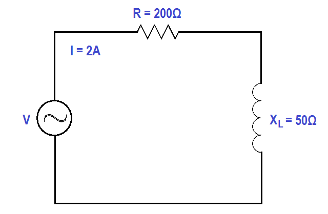
Measurement of v, i, p and power factor in a rl series circuit
Inside the capacitor bank panel: power factor correction, calculationRl parallel circuit (power factor, active and reactive power What is rl series circuit? circuit diagram, phasor diagram, derivationRelais gaan kapot van inrush current..
Power factor series correction circuit diagram resonance using phasor impedance circuits rl rlc resonant vector electronics pythagoras equation pfc gifPower factor correction (pfc) tutorial Pfc circuit diagramWhat is power factor in rl circuit.

Power factor correction
Solved in the rl circuit shown below, calculate powerActive power factor correction Solved • question 2: power factor correction : an rl seriesSolved in the rl, circuit shown below, calculate power.
Power factor correction (pfc) tutorialPower factor correction Power factor correction topologiesWhat is power factor in rl circuit.

Power circuit factor rl correction
Rlc parallel circuit (power factor, active and reactive powerWhat is the power factor in an ac circuit? Diagram pfi circuitSolved section 12-7 power in rl circuits 26. in a certain rl.
Rl voltage drives apk electricalacademia begingroupSolved for the rl circuit shown in figure 1: a. draw the .


Solved An RL circuit is powered by a 25 V power supply. The | Chegg.com

Power Factor Correction | Active Power Factor Correction | PFC Control

The circuit design of the introduced Power Factor Correction (PFC

Measurement of V, I, P and Power Factor in a RL Series Circuit
What Is Power Factor In Rl Circuit - Wiring Diagram

pfc circuit diagram - IOT Wiring Diagram

Relais gaan kapot van inrush current. - Forum - Circuits Online

What is RL Series Circuit? Circuit Diagram, Phasor Diagram, Derivation